The Leading Qualified Medical Device Supplier Directory
Discover + Source + Connect


Discover Qualified Suppliers You Can Trust
With the Qmed+ directory, you can trust you'll be connected with qualified suppliers, service providers, and consultants to the medtech industry that meet global standards for current good manufacturing practice (cGMP) regulations and quality management systems (QMS). In order to be considered for inclusion in the Qmed+ supplier directory, companies must show qualification through these criteria or proven experience working with medical device manufacturers.
Featured Products
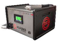
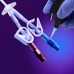
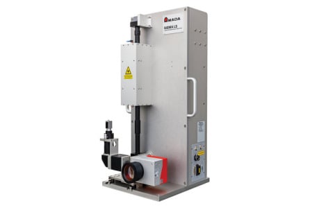
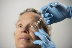
Blown Arc Series Plasma Treater
Enercon Industries CorporationImprove adhesion of inks, coatings, & adhesives on non-conductive plastic surfaces. Enercon’s Blown A...
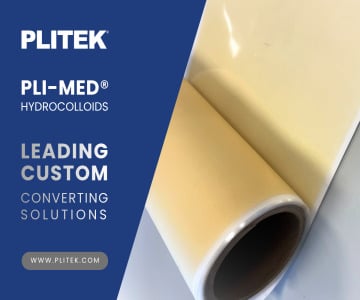
PLI-MED® Hydrocolloids
Plitek, LLCHydrocolloids are a cornerstone in modern wound care, renowned for their ability to create a conducive healing env...

FEP Heat Shrinkable Tubing
New England Wire TechnologiesFEP (fluorinated ethylene propylene) heat shrink tubing is provided in it’s expanded state and molds tightly...
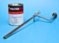
EP3HTMed: Chemically Resistant Polymer Meets USP Class VI Specifications
Master Bond Inc.Master Bond EP3HTMed fully meets USP Cl...

HLC™ Adhesives
DymaxOne-component HLC™ adhesives cure in light and darkness. These hybrid light-curable materials are engineered to polymerize in ...

Orthopaedic & Surgical Tool Tip Protection
CaplugsCaplugs offers a wide range of components to protect instruments, implants and expos...
Rapid Prototyping
JBC TechnologiesJBC provides rapid prototyping services. Customers benefit from the ability to cost-effectively test different materials a...

PTFE Forming
Rose MedicalExperts in secondary processing of PTFE to maximize the beneficial properties and meet your unique design needs. • PTFE Tippi...
Featured Companies

-comp239522.png)


The Qmed+ directory simplifies and accelerates the new supplier research and discovery process. And it's easy to find exactly what you need: Search suppliers to the medical device industry by keyword or by product or service category.
Within each supplier's directory listing, you'll find a comprehensive company overview, contact information, qualifications, products and capabilities, supplemental resources, and ways to connect.
Discover and contact thousands of pre-qualified suppliers to the medical device and in vitro diagnostics industry. Start your sourcing journey now!
Medical device and diagnostics manufacturing is a fast-moving and highly regulated industry. Today, new and exciting technologies are enabling the creation of innovative medical products that are improving patient care by leaps and bounds. At the same time, the global web of regulatory requirements governing how those products are designed, developed, and produced is growing ever more complex. As a result, it’s becoming less and less likely that individual medical technology manufacturers have all the experience and capabilities they need—from design and development to manufacturing and regulatory affairs—in house.
Medical device manufacturers today can’t do it all themselves, so they must turn to outsourcers—design firms, testing labs, contract manufacturers, component and equipment suppliers, and consulting firms—to help bring their innovations to market. But finding trusted partners in the scattered landscape of medtech suppliers and service providers is no small task.
That’s why we created Qmed, the world’s only directory of pre-qualified suppliers and service providers to the medical device and diagnostics industry. For nearly a decade, Qmed’s powerful search tool and online directory have enabled medtech manufacturers to connect with relevant partners that can help fill the gaps in their current capabilities and help speed their life-saving and -improving medical devices to market.
When medical device manufacturers turn to the Qmed directory for help in finding qualified outsource partners, they can trust they’ll be connected with suppliers, service providers, and consultants that meet global standards for good manufacturing practice and quality control, and which have relevant experience in the complex and evolving medtech industry.
In order to be considered for inclusion in the Qmed directory, companies must show qualification through some of the following criteria:
- ISO 9001 certification
- ISO 13485 certification
- CGMP compliance
- FDA registration
- Demonstrated experience with clients in the medical device or in vitro diagnostics space
Supplier News

Cretex Medical Acquires Select Assets and Capabilities of Holland Molds, Inc.
Cretex MedicalCretex Medical (www.cretexmedica...
Cadence Earns Second Consecutive EcoVadis Silver Medal for Sustainability
Cadence, Inc.Cadence, Inc. announces that it has ea...

When Are Guards Required for Medical Foot Switches Under IEC 60601
Linemaster Switch CorporationMedical foot switches control some of the most c...
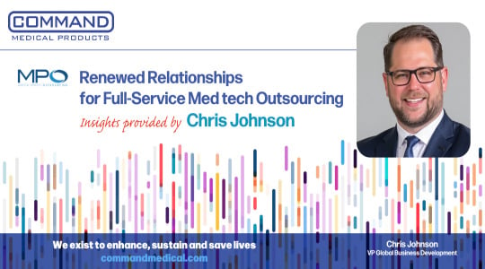
Renewed Relationships for Full-Service Medtech Outsourcing
Command Medical Products LLCIn MPO Magazine’s latest feature, “Renewed Relationships for...

Navigating the Tariff Landscape: Building Resilient Supply Chains
QosinaWhether driven by trade disputes, shifting allianc...
Improving Ultrasonic Wall Thickness Measurement with Automated Transducer Positioning
LaserLinc, Inc.Ultrasonic wall thic...
West Expands Portfolio with New Ophthalmic Drug Delivery Packaging Solution
West Pharmaceutical Services, Inc.NovaPure® 0.5 mL plunger for ISO gl...
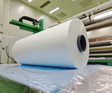
Co-Extruded Plastic Film: A Complete Guide – Benefits, Options & Applications
Achilles USA, Inc.Understanding Film Extrusion: Ho...


Ecoclean & EnPak open Clean & Pack Technology Center in Warsaw, Indiana
Ecoclean, Inc.Integrated precision cleaning and packagi...
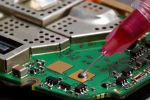
Non-Frozen, Silver Filled Epoxy Features High Thermal and Electrical Conductivity
Master Bond Inc.Master Bond EP6STC-80 is a...